

© Greenstick Enerygy Limited 2019 website design by Geoffrey Miller : www.flamboroughmanor.co.uk
Greenstick technology for offshore construction
by Gennady Meltsov PhD ©
Greenstick piles can be used in three ways:
- As a flexible mooring, an alternative to anchoring with chains;
- As rigid elements of offshore structures;
- For the construction of single point mooring systems, underwater floating storage.
1. Usage of Greenstick offshore structures.
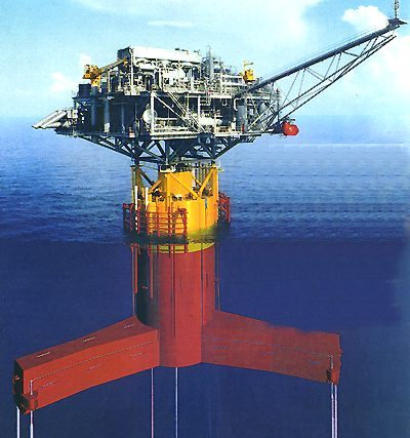
1.1 Mooring of floating platforms. The usage of thick-walled pipes as flexible connections, diameter 127mm, is well-known [8]. One of the structures developed in the United States used a flexible tubular pipe connection of 24 pipes with diameter D = 475mm. Installation to be used at depths of 250m to 500m. British designs performed well on tests Keysab installation, see Fig .1. The unit is designed to work in the North Sea at depths of up to 300m.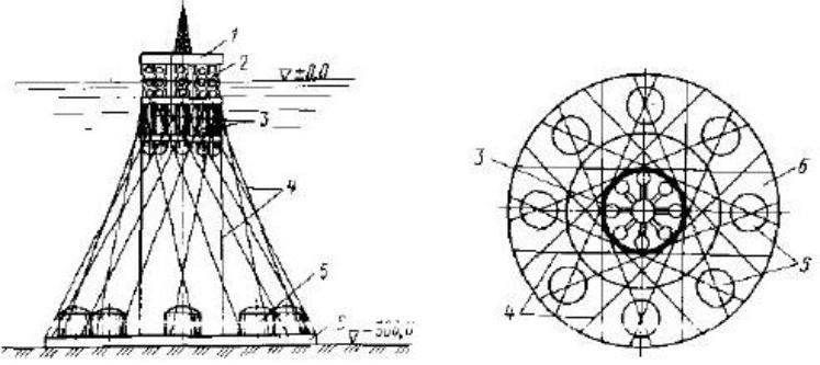
Figure 1 Project rig Keysab. 1- topsides, 2-stabilizing columns, 3 pontoons, - pipes 4, 5 storage tanks, 6- bottom annular array.
Variants of the structure can be calculated with the number of options for 24-72 flexible connections. The body of cylindrical
shape with a central column supports the superstructure or ring of eight stabilizing columns, as in Figure 1, with lower united
distribution belt and deck structure above. The material of annular array is reinforced concrete, located on cylindrical tanks for
oil volume of 240,000 m3.
Displacement is 150,000 tons. Under the influence of 16m sea waves, movement of the installation does not exceed 0.6m
(0.2% of the depth of the sea), and the amplitude of the vertical displacement of not more than 0.9m.
By analogy with the construction described above, Greenstick piles can be used for the anchoring of floating objects. Thus, the
pile used to penetrate the seabed in conjunction with the Greenstick joint may be screw piles, sucked piles or other types
depending on the soils of the sea bed. The pile portion located above the bottom may be formed as a thick steel pipe with a
diameter of up to 500mm.


Table 1. A comparison of physical and mechanical properties of fiberglass and steel.
The tensile strength of fiberglass (basalt fiber) section is not lower than metal (see table 1). The modulus of elasticity of
fiberglass is 10 times lower than that of steel, and therefore the ultimate deformation of centrally compressed fiberglass is
much more than the metal that is essential for anchoring pipes offshore structures in tidal seas. Thick steel pipes with a
diameter of 500 mm and a diameter up to 700mm fiberglass and more may be used instead of chains and ropes. Increasing
the diameter of the pipe without buckling, leads to the possibility of a greater tensile load at the same time retaining the ability
to straighten to its original state if bent.
Thanks to the fact that the weight of fiberglass is 4-5 times lower than that of steel, delivery and installation of GRP pipes
significantly reduce the cost of construction. For example, the cost of renting the floating crane lifting capacity of 300t in
Europe is EUR 200 000 per day, regardless of downtime caused by bad weather and transportation. Whereas FRP/GRP pipe
production may be assembled on the coast and where tenth meters long pipes may be produced. This minimizes delivery, pipe
connection cost and increases the reliability of structures.
The technology for the manufacturing of steel pipes used in offshore construction involves a large amount of welding,
reducing the reliability of structures and require protection against corrosion. The wall thickness of the manufactured steel
pipe is limited to the capacity of bending machines. The huge weight produced by steel pipes and structures has led to the
need to build expensive specialized boats for building on the shelf. Also, the weight of steel structures that require transport
and assembly limits the possibility of building at greater depths. The production line of winding FRP/GRP pipes can be located
on the shore and allows production of large diameter seamless pipes of virtually unlimited length and any wall thickness (see
fig.17).
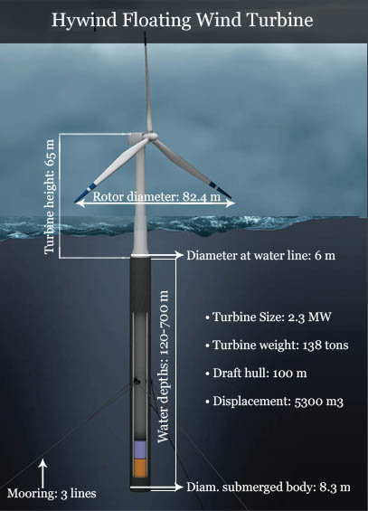
Figure 2 Floating Wind turbine Hywind, Statoil.
HyWind wind electric generator installation (see Fig. 2) requires
anchor chains of three sucked piles or Dredge anchors,
depending on the depth and soil. Alternatively, Greenstick piles
can be used to anchor a HyWind Structure designed for depths of
120 to 700 meters.
We propose a new concept (see. Fig. 3) for using floating wind
turbines at shallower depths. Working on the principle of the two-
handed sword, the base of the floating wind turbine is designed
as a pendulum whose center of mass is located at the point
where chains attach to the underwater part of the structure. It is
known that at depths deeper than half the length of a sea wave
there is no wave pressure. Reducing the length of the pipe
increases the weight of the counterweight attached (see figure 3).
This extends the scope of floating turbines at shallower depths.
At the same time, secure "handle" piles are attached, hinged on
both sides. Regardless of the movement of the sea surface
caused by wind or tide the platform remains steady.
The volume of water displaced by the pendulum must be greater
than the weight of the whole structure, taking into account the
trough of the wave at low tide, when the volumetric weight of the
structure located above the water level increases.
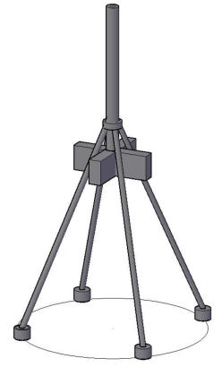
Figure 3 Greenstick Concept for floating wind turbines.
The volume of the counterweight can be reduced by reducing the
weight of the structure. A significant effect can be achieved by
using FRP/GRP as a material for wind turbine masts. Volumetric
weight of FRP/GRP is 4-5 times less than steel.
Attaching the handles of Greenstick piles to the distribution ring
may be provided by usage of currently patented devices and are
not shown. Due to the fact that the pendulum is capable of
deviating under the influence of an unexpected load, to return to
the original position by the counterweight design, Greenstick piles
indicated in Fig. 3 can be used in the Far North and take the load
of ice floes and single large waves. Changes in the level of tides
has almost no effect on the vertical movement of structure due to
the relatively small volume of water displaced by the mast during
high tide, compared with the volume of the counterweight.
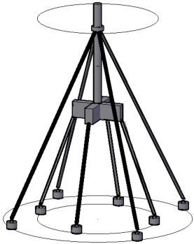
Figure 4 Concept Greenstick reason for floating wind turbine with
additional anchoring belts.
When retrofitting belts with stretch marks can be greatly reduced
oscillations of a wind turbine’s top.
1.2 Mooring of gravitational structures.
Truss structures with Greenstick piles may be used for increasing
the rigidity of the upper part of rigid offshore structures. Usage of
Greenstick piles reduces the radius of circulation and the drift of
the wind turbine as compared with traditional anchoring chains.
Most importantly, the anchoring Greenstick can significantly
reduce the distance between the wind turbines and thus the area
occupied by wind farms minimizing environmental damage. In
addition, anchoring chains involves placement of anchors at a
distance of hundreds of meters, which can lead to tangling cables
and chains, exacerbated by lack of vessels to anchor in stormy
weather in the area. Greenstick can provide a high mooring
ability, if necessary, used with floating base with anchored float
located in the zone of waves and tides.
Figure 5. The drilling platform Moses TLP with tension anchorage
Because of the large surface area, underwater floats are subject
to considerable wave loads. Tidal fluctuations in the North Sea
can be more than 7.5m off Scotland and Norway, which is why the
anchoring of the floating base must be flexible. At considerable
depths thick steel and GRP pipes can be used.
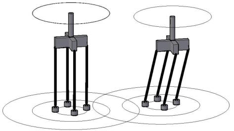
Figure 6 Mooring a flexible floating platforms by Greenstick
piles at a maximum (left) and minimum (right) tides.
Figure 7 (below) shows the construction of the drilling
platform Mandrill projected for the company Man
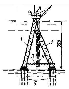
Figure 7. Drilling platform “Mandrill”. 1- legs forming A-frame,
2-hinged leg , 3- screed, 4- risers, 5- piles.
Alternatively, instead of the closely spaced bushes (5) high
efficiency suction piles may be used.
Screed (3) can be placed over the vertically mounted Greenstick
piles, connecting piles in pairs.
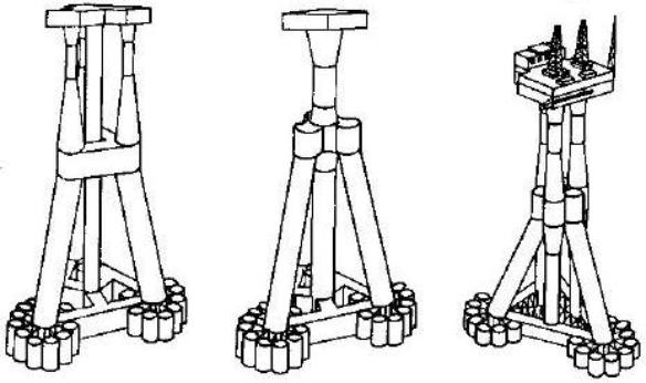
Figure 8 Gravitational concrete platform Trypod300 for depths up to 300m.
Reinforced concrete structures on Fig. 6 have considerable weight and are fragile because of their size. Transportation and
installation of such structures is very expensive. For example, a floating crane rental costs $200,000 per day in addition to the
delays caused by bad weather and transportation to the required location. The advantage of Greenstick piles is the possibility to
install piles alternately, thanks to the joint which allows assembly into spatial structures with high load capacity and large mass.
Likewise, rigid structures can be created with Greenstick piles, as shown in fig. 8. Ground structures experiencing significant
vertical load may include one or more central vertical supports / piles. Construction is performed in the following sequence. After
a vertical insatllation of three piles, the top is turned in to an inclined position and is fixed in the form of a pyramid. The top pile is
in the form of a metal structure fixed to the vertex of the pyramid. Precise positioning of installed piles may be provided by
floating guides with folding locks.
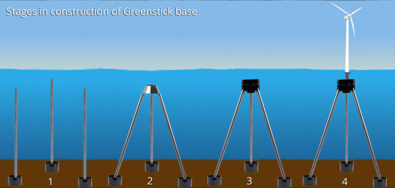
Figure 9. The construction sequence for a solid Greenstick base
Then, by towing and flooding, a block may be mounted on top of the pyramid to support the wind turbine. Piles can be made
from standard pre-stressed concrete tubes with a diameter 1.2, 1.6, 3.0m., with a significant bearing capacity. Piles may be used
as a hollow shell and filled with concrete which significantly increases their load bearing capacity (see fig. 16). Section shells are
joined by means of flanges. Pipes flanges may be welded together and provide water tightness and towing capability of chain of
pipes on the water with a minimum amount of floats. After arrival on site, they can be submerged in a sealed condition, which
ensures minimum weight, or flooded and, after installation in the correct position, then filled by concrete. Reinforced concrete
pipes are widely used in the construction of bridges and ports structures.
Genna Meltsov can present this synopsis at
seminars and conferences on request. His
English is excellent; however, please accept
that this document is not written in his
native tongue and may contain a few
anomalies in translation.
Four short papers by Gennady Meltsov PhD
[Note: all in Russian]
1. Prirodni_umovi
2. Основной вариант
3. Узлы и детали1
4. Узлы и детали2
Greenstick Resources in PDF format available for download: