

© Greenstick Enerygy Limited 2019 website design by Geoffrey Miller : www.flamboroughmanor.co.uk
Greenstick technology for offshore construction by G. I. Meltsov ©
Continued
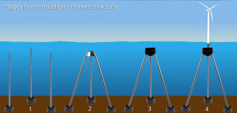
Figure 9. The construction sequence for a solid Greenstick base
Then, by towing and flooding, a block may be mounted on top of the pyramid to support the wind turbine. Piles can be made
from standard pre-stressed concrete tubes with a diameter 1.2, 1.6, 3.0m., with a significant bearing capacity. Piles may be used
as a hollow shell and filled with concrete which significantly increases their load bearing capacity (see fig. 16). Section shells are
joined by means of flanges. Pipes flanges may be welded together and provide water tightness and towing capability of chain of
pipes on the water with a minimum amount of floats. After arrival on site, they can be submerged in a sealed condition, which
ensures minimum weight, or flooded and, after installation in the correct position, then filled by concrete. Reinforced concrete
pipes are widely used in the construction of bridges and ports structures.
1.3 Mooring of mono piles
Mooring of mono piles, see fig.9, can be carried out in order to:
- reduce the displacement top mono piles;
- reduce material consumption by reducing its diameter;
- provide the possibility of building at great depths.


Figure 10 Mooring of mono pile. Right - isometric, left - a top view. Hinges in the area of the hoop are not shown.
The number and arrangement of the hoops may be varied depending on the mono piles material, intersection, loads,
depth, geological data, etc. The connection of the hoop with Greenstick mooring piles has been designed and is in the
process of being patenting.

Figure 11 Scheme of anchoring floating bases: a is the point of rotation of the pendulum; b- the same with additional
anchoring; c-strain diagram; d- decrease strain anchoring, 1-6 piles Greenstick.
The scheme shown in fig. 11 illustrates the base with positive buoyancy even in the case of rollback wave at low tide. In
the worst case, flexible Greenstick piles bend, but do not compress. Horizontal loads P1, P2 will fasten the base down.
A Greenstick pile is flexible in deep water: compression may cause it to bend, but not to crack.
1.4 Construction of deep-water berths and oil
storage point.
Figure 12 Single point floating pier in Tazerka. Single anchor
leg mooring (SALM) Greenstick pile can be a major part of
the Single Point Mooring.


Figure 13, left, where1- floating body, 2- turning headroom, 3- helicopters
platform, 4- crane boom; 5- flexible dispensing conduit, 6- mooring, 7- fenders,
8- truss support, 9- ballast tanks, 10 - joint , 11- bottom support, 12- pipeline.
Figure 14, below. Single point mooring with a rigid floating mooring truss. 1-
bottom anchor support, 2- joint, 3- tubular retaining connection, 4 mooring
swivel pipelines, 5- hinge, 6 tanker, 7-farm, 8-floating pontoon, 9 pipeline.
1.4 Floating storages
Figure 15 Floating types of semi-submersible vessels to 70 000 tons (a) and 40 000 tons (b) 1-turntable, 2- rotary dispenser, 3-
dispensing conduit, 4- topsides, 5- stabilizing columns, 6- storage, 7 - anchor chain, 8- anchor the bottom, 9- hoses, 10- main pipeline,
11- anchor.
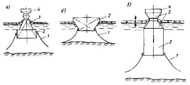
Floating storage, designed for operation in Arctic seas, differs from others by cone-shaped shell or stabilizing columns at the
waterline (fig. 16). The vertical action distorts facilities on a moving ice field (downward or upward, depending on the position of the
conical surface) and causes bending of the field with destruction at lower horizontal loads on structures than is the case if in the form
of cylindrical obstacles.

Mooring Systems [8] http://coolarcticmoorings.weebly.com/mooring-systems.html
The choice and dimensions of mooring systems depends on several factors. Important aspects when considering the dimensions of
mooring lines and the foundations of these lines are economics, environmental conditions, availability, requirements and other
installations within the area. Numerous other different mooring systems have been developed over the years, of which a selection
are presented here:
Spread Mooring System
A typical Spread Mooring system utilizes a set of mooring lines distributed over the bow
and stern of the vessel to anchors on the seafloor. The vessel is positioned in a fixed
heading, which is determined by sea and weather conditions. The symmetrical
arrangement of anchors helps to keep the ship on its fixed heading location. The spread
mooring system does not allow the vessel to weathervane, which means to rotate in the
horizontal plane due to wind, waves or current. Spread mooring can be used in any water
depth, on any vessel, in an equally spread pattern or a group.

Internal Turret Mooring System
This system is integrated into the forward end of a tanker or barge and is supported on a large roller bearing, located either inside
a monopole, towards the bottom of the vessel, or at deck level. The outer rotating race of the bearing is connected to the vessel,
while the inner race is attached to the fixed part of the turret. Above deck lever, a manifold structure enables connection between
the lower turret and the swivel stack.
External Turret Mooring System
The external Turret Mooring system is made up a steel box type structure that is extended outside the bow or stern of the vessel,
providing a foundation for a rotating bearing arrangement and a turret. The mooring chains and fluid transfer are attached to a
chain-table at the bearing. The chain legs are anchored to the seabed either by anchors or piles. Product and utility connections
are made between the facilities on the tanker and the seabed via a swivel stack in the turret, allowing the tanker to weathervane
around the fixed part whilst continuing production.
Single Anchor Leg Mooring (SALM)
The floating buoy is anchored to the seabed by one single anchor leg, connected to a base type anchor point (ballasted and/ or
piled). The buoy can be attached to the base by either one single chain or by a chain or tubular column. The floating buoy of the
system is anchored to the seabed by one single anchor leg which is connected to a base type anchor point. The base be attached
to the buoy by a single chain or by a chain or tubular column.
A SALM system prevents collision damage to the swivels by placing them underwater and below the keel level of the tanker. The
underwater swivels do however have maintenance disadvantages. To prevent the flexible loading pipe clashing with the mooring
chains the catenary is replaced by a single, nominally vertical, tensioned chain mooring leg. In shallow water the fluid swivels are
on the base. In deep water the fluid swivels could be attached part way up the mooring leg. This would ease maintenance of the
swivels and the flexible pipes from the swivels to the tanker.

Catenary Mooring
Generally with this system uses four or more mooring lines at equally spaced angles. The mooring lines mostly have a catenary
shape. The catenary mooring system is the most commonly used system in shallow to deep water. The part of the mooring line
that is suspended in the water will take on a catenary shape. Depending on the water depth, the weight of the mooring line and
the force applied to the mooring line at the failed, the length of the suspended mooring line can be determined. The large line
geometrical changes make catenary mooring systems subject to significant dynamic effects due to transverse drag load. The
restoring forces in a Catenary Mooring System are generated by the weight of the mooring system. The mooring lines in catenary
mooring systems are commonly composed of steel rope and chain segments.
Taut mooring
The Taut mooring systems are consistently spaced as Catenary Mooring systems. The major difference between Catenary
Mooring and Taut leg mooring is that where Catenary Mooring arrives at the seabed horizontally, the Leg Mooring arrives at the
seabed at an angle. This means that in Taut Leg Mooring, the anchor point has to be capable of resisting both horizontal and
vertical forces, while in a Catenary Mooring, the anchor point is only subjected to horizontal forces. The restoring forces in the
Taut Mooring system are generated by the elasticity of the mooring line.
The advantage of this system is that the footprint of the Taut Mooring system is smaller than the footprint of the Catenary
Mooring System, which results is a smaller mooring radius for Taut Mooring systems, which is especially an advantage in deeper
water. Another advantage is the better load sharing between the adjacent lines, compared to the catenary system, which results
in an improving of the efficiency of the system.


Figure 17 The complexity of the installation of
anchoring multiple objects

2. Recommended materials and components to withstand the loads of
offshore structures.
2.1 Concrete columns shell diameter 1.2, 1.6, 3.0m Model projects 3.501.1-214 Hollow round reinforced concrete pipes gives the values of the bearing capacity of piles hollow and filled with concrete, sufficient for the design of structures using Greenstick piles.

Figure 18. The bearing capacity of piles with a diameter 1.6 m. At the top and 3.0m at the bottom. Solid line – hollow pipes,
dotted line - filled with concrete.
As can be seen from the graphs [1], see. fig.18, a pile with outer diameter of 1.6m, shell 12sm can withstand the bending
moment in the hollow 500tm and 800tm filled in with concrete. For compressive load – 1500ton and 3300ton respectively. 3.0m
diameter piles withstand bending moment to 1800tm in hollow and 4600 tm in the state filled with concrete and compressive
load of 3000 and 12 000 tons respectively. Piles of diameter 3.0 with sealed ends may be towed out to sea, so taking into account
the displaced water meter piles has positive buoyancy + 4.39t.
2.2 Comparison of steel and fiberglass pipes with chain and rope.
The biggest chain gauge in the company directory Vryhof [2] is 185mm. Weight of 1m anchor’s chain with diameter 185 mm is
750 kg. Breaking load level - 27383 KN (2738 tons). Cross-sectional area with a diameter of 185mm unit is 268.8sm2. This is
equivalent to the cross section of 475mm diameter steel pipe with a wall thickness of 18mm.

At the same time, according to the US Federal Specification RR-C-271, the workload of the chain sling and shackle should not
exceed 1500t Cable, a nominal diameter of 153mm (6 inches) minimum breaking load of 2270 KN. Nominal weight of 119.7kg/
m. The estimated load is given to the calculation of the lifetime of a cable - 10 years. The largest synthetic ropes of ultra-high
molecular polyethylene with a diameter of 187 mm have a maximum breaking load 24812KN / Weight 17.2 kg / m. Strength
polyester stretch anchor diameter 245mm is 20307KN. Data referred to the spliced cables. Given the slack, required chain, wire
rope, at times longer than the length of the pile Greenstick the same cross-sectional area of steel. Because of the slack chain,
wire rope is a significant radius of gyration moored object. Floating offshore structures moored by Greenstick piles have tenth
times smaller radius of circulation in comparing with mooring by chain. Thus, elastic modulus of fiberglass is significantly lower
than that of steel. This allows us to recommend wound thick fiberglass pipe for its usage with the advantage of significant
tensile forces. For reinforcement of pipes, basalt fibers can be used having greater strength than fiberglass and with a better
permeability to prevent micro penetration.
2.3 Types of piles used to Greenstick offshore construction
2.3.1 Suction piles
Figure 20 (left) Suction steel pile


Figure 21 (below) Suction pile of
Dong, United Kingdom.
Known suction pile generally
cylindrical with a top skirt, as well as
the patented design Dong, cm.
Figure 21. Known patented suction
pile with reinforced concrete pile
element, see fig22.
Figure 19. Fiberglass winding pipe with inner
diameter 3.0m.

Figure 22. Suction reinforced concrete pile of Daoda,
Hongkong.
2.3.2 Screw piles
Screw piles are widely used in sea construction from the middle of the 19th century. The most famous is the construction of the Mitchell’s lighthouse in the U.K. In the Soviet era, in Odessa port, a pier for raw sugar was built [4] using screw piles with a diameter of screw- 2.4m, diameter of the trunk- 1.02m, the wall thickness of 12 mm. The mass of 38m length pile was 13.6 tons. Tess showed the carrying capacity for the vertical load - 800tonn. The most efficient usage of screw piles is for temporary structures because the force required for unscrewing the pile, is times lower than used during screwing.
2.3.3 Mono piles
To reduce the displacement top mono piles can be used anchoring piles Greenstick scheme cm. fig. 11.
2.4 Hinges
Due to the fact that the handle is pivotally connected to the Greenstick pile, it works just on tensile loads. The element operating in a
complex stress state is the hinge. Fig. 24 shows hinge bridges, hinged and hingeless type, with perceived much greater load than the
greatest anticipated load in the Greenstick pile for heavy Arctic conditions.
Figure 16 Floating passive (a, b) and active protection against ice. 1-
anchor`s chains, 2- housing, 3-ice-breaking waist, 4- topsides.


Figure 23 Hinges of Millennium Bridge in London

Figure 24 Share and bearing hinges
3. Conclusion and recommendations.
Greenstick piles are high technology structural elements which can reduce the cost of construction by reducing the time of installation, but with load-bearing properties applicable to the appropriate standards used in modern offshore construction. Greenstick piles can be used in the construction of offshore foundations of fixed and floating drilling rigs and power generation plants, underwater storage and single point moorings. Greenstick piles can be: driven, controlled drilled, uncontrolled drilled, inserted pile, grouted pile, belled pile, suction pile, screw pile. In this connection, Greenstick pile can be used in any engineering-geological conditions - from mild to saturated soils and rock. Greenstick pile elements can be made of steel, concrete, and composite materials. The most effective use of Greenstick piles is for mooring of shelf structures sensitive to deformations and displacements. Greenstick piles significantly reduce radius of circulation and vertical movements of moored floating objects. Chained mooring involves large areas and is particularly difficult in the case of mooring of several adjacent objects and the need to anchor ships (see fig.17). The use of Greenstick piles solves this problem. The projected service life of offshore facilities far exceeds the life of the chains and ropes. Greenstick piles do not have such restrictions and have greater reliability in comparison to chains. The use of Greenstick piles causes less environmental damage than the chains, cables and ropes mooring, especially in the case of dredge anchors.
Figure 25 Universal joint used in piles Greenstick.
Bolted connections are not shown.
List of sources used.
1. Model project, a series of 3-501.1-124 Hollow round piles and piles of shell diameter 0.403.0 m of pre-stressed and reinforced concrete for conventional
bridge supports. Transportation Ministry, Moscow 1980.
2. Catalog of Anchors - www.Vryhof.com
3. Patent Grenstick, 2013, 144pp.
http://patentscope.wipo.int/search/en/detail.jsf?docId=WO2013150276&recNum=6&maxRec=&office=&prevFilter=&sortOption=Pub+Date+Desc&querySt
ring=&tab=PCT+Biblio
4. Marchenko A.S.Morskie port facilities on soft ground "Transport" .M.1976, 192ctr.
5. Systems anchoring http://coolarcticmoorings.weebly.com/mooring-systems.html
6. Sox BD, Pravdivets YP Facilities of continental shelf. Moscow, .ASV 277str. 2003
7. Grudnitskii GV, Grudnitskii SG, SI Egorov, R. Mamutov Offshore Oil and Gas point moorings. Moscow, “Energy Press”,2011,367pp.
8. ThomasH. Dowson Offshore Structural Engineering.Prentice hall, USA. 1986. 287 pp
9. Byron Byrne, Guy Holsby. Helical piles for offshore wind turbines .26 pp. Oxford University, 2010.